10.1. Transfer Functions and Gamma
10.2. The gAMA Chunk
10.3. Encoding Gamma
10.4. Gamma Gotchas
10.5. Chromaticity
10.6. Color Management Systems and sRGB
10.7. ICC Profiles
Anyone who has transferred images between a PC and a Macintosh--or even simply viewed on one platform an image created on another--has probably noticed one of the little gotchas of the computer world: images don't look the same on all systems. Images created on Macs tend to look too dark on PCs; images created on PCs tend to look too bright and washed out on Macs. A pure yellow on one machine may have an orange or greenish tint on another. Even on a single machine there are usually obvious changes in brightness and color as the monitor (CRT) warms up, not to mention when the user adjusts the screen controls. And in the absence of tedious calibration procedures and high-end color-conversion software, what comes out of the printer is, at best, only a vague approximation of what the screen shows.
PNG certainly doesn't solve all of these problems, but it does provide image authors with the means to minimize many of them, as long as the editing and viewing software is written properly. As recently proposed standards are approved and implemented in hardware, from graphics cards, to monitors, to printers and scanners, there is reason to expect that platform-independent color will become the norm, not the exception, in the new millennium.
To understand the solutions, one must first become acquainted with the problems. I won't attempt to cover the subject in detail; an entire book could be written on it--and, indeed, Charles Poynton has done just that. But I will give a brief overview of the main issues and explain how some of the features of the Portable Network Graphics format fit into the picture. I may even mention some physics and an equation or three, but you shouldn't need a technical degree to be able to understand the basic ideas.
The ultimate goal of the entire process is for the light that leaves your monitor to produce the same perception as the light that originally entered the camera would have if it had entered your eyeballs instead. Alternatively, for images created with an image-editing application, the goal is for your display to produce the same perception (and basically the same light) as the artist's monitor produced while he was creating the image. Clearly this involves both the encoding process performed by the editor or conversion program that writes the image file, and the decoding process, perfromed by the viewer or browser that reads and displays the image, as well as aspects of human physiology and psychology. We'll refer to the combination of the encoding and decoding processes as the end-to-end process. PNG's role is to provide a way to store not only the image samples, that is, the color components of each pixel but also the information needed to relate those samples to the desired output of the display. A decoder that has both that information and knowledge of how the user's display system behaves can then deduce how the image samples must be transformed in order to produce the correct output.
Storing the image samples themselves is easy. The tricky part is figuring out the two additional pieces of critical information: when encoding, how the original light is related to the samples, and when decoding, how image samples are related to the display's actual output (i.e., the reproduced light). The fundamental problem is that working with and storing light is nearly impossible; instead, light is typically converted to electrical signals. Indeed, there are several more conversions along the way, each of which potentially modifies the data in some way.
As a concrete example, in an image captured via a video or electronic camera, light entering the camera is first converted to analog voltages, which are in turn converted to other voltages representing digital ones and zeros. These are stored in an image file as magnetic fields on a hard disk or as tiny pits on a CD-ROM. For display, the digital data in the file is optionally modified by the viewing application (this is where gamma correction and other tweaking is performed), then possibly converted again according to a lookup table (LUT), then generally converted by a graphics card (``frame buffer'') back to an analog electrical signal.[77] This analog signal is then converted by the monitor's electronics into a directed beam of electrons that excites various phosphors at the front of the monitor and thereby is converted back into light. Clearly, there is a bit of complexity here (no pun intended).
[77] Early PC graphics cards (the ``CGA'' and ``EGA'' adapters, for example) communicated with the monitor digitally. Ironically, the burgeoning popularity of flat-panel displays and digital television is driving manufacturers back to using digital links between the frame buffer and display. As of early 1999, the standards and products were rare to nonexistent, but they're coming.
But all is not lost! One can simplify this model in several ways. For example, conversions from analog to digital and from digital to analog are well behaved--they introduce minimal artifacts--so they can be ignored. Likewise, the detailed physics of the monitor's operation, from electrical signal to high-voltage electric fields to electrons to light, also can be ignored; instead, the monitor can be treated as a black box that converts an electrical signal to light in a well-defined way. But the greatest simplification is yet to come. Each of the conversions that remain, in the camera, lookup table, and monitor, is represented mathematically by something called a transfer function. A transfer function is nothing more than a way to describe the relationship between what comes out of the conversion and what went into it, and it can be a fairly complex little beastie. The amazing thing is that each of the preceding conversions can almost always be approximated rather well by a very simple transfer function:
output = inputexponentwhere the output and input values are scaled to the range between 0 and 1. The two scaling factors may be different, even if ``input'' and ``output'' both refer to light; for example, monitors are physically incapable of reproducing the brightness of actual daylight. Even better, since the output of one conversion is the input to the next, these transfer functions combine in a truly simple fashion:
final output = ((inputexponent1)exponent2)exponent3 = inputexponent1*exponent2*exponent3This example happens to use three transfer functions, but the relation holds for any number of them. And the best part of all is that our ultimate goal, to have the final, reproduced output light be perceived the same as the original input light, is equivalent to the following trivial equation:
exponent1*exponent2*exponent3 = constantOr in English: all of the exponents, when multiplied together, must equal a single, constant number. The value of the constant depends on the environments in which the image is captured and viewed, but for movies and slides projected in a dark room, it is usually around 1.5, and for video images shown in typical television or computer environments, it is usually about 1.14. Since the viewing application has the freedom to insert its own conversion with its own exponent, it could, in principle, ensure that the equation holds--if it knew what all the remaining exponents were. But in general, it lacks that knowledge. We'll come back to that in a moment.
In practice, images may be created with any number of tools: an electronic camera; the combination of a classic film-based camera, commercial developing process, and electronic scanner; an image-editing application; or even a completely artificial source such as a ray-tracing program, VRML browser, or fractal generator. To a viewing application, a file is a file; there is rarely any obvious clue as to the true origins of the image. In other words, the decoder can have no reasonable expectation of divining any of the transfer functions that came before the image data was saved to a file, even if it asks the user for help. The decoder's sole concern must therefore be the conversion of samples in the image file to the desired output on the display.
We'll come back and deal with encoders in a little while. For a decoder there are only two cases: either the file contains the additional information about how the samples are related to the desired output, or it doesn't. In the latter case, the decoder is no worse off than it would have been when dealing with a GIF or JPEG image; it can only make a guess about the proper conversion, which in most cases means it does nothing special.
But the case in which the file does contain conversion information is where things finally get interesting. Many types of conversion information are possible, but the simplest is a single number that is usually referred to as gamma. Gamma is a Greek letter (γ) that traditionally represents the exponent in the first equation I gave; the only problem is that, as we've seen, there are several exponents in the end-to-end process, and different people use the term ``gamma'' to mean different things. I will use ``gamma'' to refer to the exponent relating the image data and the desired display output. Not surprisingly, this is how PNG's gAMA chunk defines gamma, too.[78]
[78] Version 1.0 of the PNG specification discussed gamma in terms of the end-to-end transfer function from source to final display. This was deemed impractical and not necessarily indicative of real-world practice, so version 1.1 of the specification clarified all of the gamma-related discussion and reserved the actual term ``gamma'' solely for the usage described here.
PNG's gAMA chunk basically says: if your overall display system's exponent (generally a combination of the system LUT exponent and the monitor or CRT exponent) is the same as the inverse of this gamma value, then the samples in the file are ready to go and need no further correction.[79] If not, the decoding correction can be computed from the product of the overall display-system exponent and the stored gamma value.
[79] Practically speaking, values that are within about 5% of each other may be considered ``the same.''
More precisely (and here we get into a bit of mathematics that will mainly be of interest to application developers), the stored gamma value represents the following relationship between the image samples and the desired output light intensity:
image_sample = light_outgammaor:
image_sample1 / gamma = light_outOnce again, bear in mind that light_out and image_sample are scaled to the interval between 0 and 1; that is, if the sample depth is 8 bits, the file samples range between 0 and 255, so image_sample is obtained by dividing a given file sample by 255, in floating-point arithmetic.
The decoding pipeline is represented by this expression:
image_sampledecoding_exponent * LUT_exponent * CRT_exponent = light_outThe decoding_exponent is simply the gamma correction that the application applies; the combination of the other two exponents is the ``overall display system's exponent,'' to use the language with which we began this section. Notice that the preceding equation and the one before it are very similar--in fact, they imply the following relationship between the exponents:
(1 / gamma) = decoding_exponent * LUT_exponent * CRT_exponentor, equivalently:
decoding_exponent = 1 / (gamma * LUT_exponent * CRT_exponent)The gamma relationship given in English at the beginning of this section simply says that if the product on the right side of this equation equals one (which means decoding_exponent also equals one), then no further conversion is necessary--the image samples are ready to go as is. On the other hand, if the right-hand side of the equation differs from one, then that value is decoding_exponent and is what the decoder uses to correct the image samples before sending them to the display system:
display_input = image_sampledecoding_exponentNote that this procedure applies to each red, green, and blue value in a truecolor image or to each palette value in a colormapped PNG. But it does not apply to transparency values in an image with an alpha channel or a tRNS chunk; alpha samples are always assumed to be linear. Implementors should also be aware that there is no need to perform a computationally expensive exponentiation for every pixel in the image, or three times per pixel for an RGB image! At most, there are only 65,536 possible sample values (for a 16-bit grayscale or 48-bit RGB image) and usually no more than 256, which means that gamma correction can be accomplished via a simple lookup table computed when the gAMA chunk is read.
That brings us to the gAMA chunk itself. Its contents are quite simple: a 4-byte, unsigned integer equal to gamma multiplied by 100,000 and rounded to the nearest integer. So if gamma is 1/2.2 (or 0.45454545...), the value in the gAMA chunk is 45,455. There can be only one gAMA chunk, and it must appear before any IDATs and also before the PLTE chunk, if one is present.
As a practical matter, there is one more piece to the decoder half of the gamma puzzle. The issue of exponents for the lookup table and monitor on various systems is more complex than it should be, mainly because different systems use the term ``gamma'' in strange and sometimes sneaky ways. Table 10-1 summarizes the issue for some common platforms.
| Table 10-1. Gamma Comparison Across Common Platforms |
| Platform | LUT_exponent | Default LUT_exponent |
CRT_exponent | Default gAMA |
| PC | 1.0 | 1.0 | 2.2 | 45,455 |
| Macintosh | g/2.61 | 1.8/2.61 | 2.2 | 65,909 |
| SGI | 1/g | 1/1.7 | 2.2 | 77,273 |
| NeXT | 1/g | 1/2.2 | 2.2 | 100,000 |
The key thing to note, aside from the differences in default gAMA values across platforms, is that both Mac OS and SGI IRIX allow the user to modify a ``system gamma'' setting that not only differs from the gamma definition we're using but also differs between platforms. These ``gamma'' values modify the lookup table, and SGI's is straightforward: LUT_exponent is simply the inverse of the SGI ``gamma'' value, which is denoted g in Table 10-1. (NeXT workstations use the same convention as SGI, but the only way to modify their setting is with third-party utilities.) The Macintosh, on the other hand, not only defines its ``gamma'' as directly proportional to LUT_exponent but also divides it by a constant factor (2.61). Thus, while the default Macintosh ``gamma'' of 1.8 appears close to SGI's default of 1.7, the actual lookup table exponents corresponding to these defaults are 1.8/2.61 and 1/1.7, respectively.
That wraps up gamma correction on the decoding side of things, but what about encoders? After all, they must put the proper information into the PNG file in the first place, so that decoders can do their job correctly. The issue is more complex than for decoders, and not only because there are so many ways to generate an image. Consider the process of creating an image in an editor, which might seem the most straightforward case since it involves, in some sense, exactly the opposite procedure from that employed by the decoder. That is, the artist manipulates the image so that the displayed output has the desired appearance, then saves the result in a file with the proper gamma. Ordinarily, the editing application would simply write a gamma value that corresponds to the artist's display system. But if the image in question originated on another system, some editors will actually preserve its gamma setting by using a decoding_exponent for all manipulations on the artist's system--just as a normal viewer would. Thus the artist sees an image displayed in her own ``gamma space,'' but the underlying image samples actually remain in the gamma space of the original system.
The case of an electronic camera that writes image files directly turns out to be the simplest possibility; as noted earlier, the camera has its own transfer function and exponent, and the camera's manufacturer should know precisely what that exponent is. When the camera saves an image, whether in PNG format or something else, the proper gamma value is simply the one that will make the end-to-end product of exponents equal to the correct constant--which, you'll recall, is around 1.14 in the case of images captured in a TV studio environment and intended for display on a computer system. But even under different lighting conditions, the camera knows what the conditions are and can correct for them accordingly, perhaps via preset gamma settings for half a dozen situations, for example: dimly lit, flash-illuminated, studio lighting, sunny day (high contrast), bright cloudy day (lower contrast), and so on.
For images captured with a traditional camera and scanned from a print, the issue is slightly fuzzier. If the scanner writes directly to an image file with no user control of brightness and contrast, the case is exactly analogous to that of the electronic camera: the scanner manufacturer knows what its transfer function is and can encode the proper gamma value in the file. But most scanners operate in conjunction with editing software that allows the user to tweak not only gamma-related settings but also color balance and saturation; this case is more like the first one considered (regardless of whether the user considers himself an ``artist'').
Ironically, images that are generated completely artificially are the most complicated case. Most calculations on artificial scenes, including those for VRML and ray-traced worlds, are done with ``linear lighting'' that would correspond to a gamma of 1.0. But in creating the scene, the artist usually makes adjustments based on how it displays on her system, and if she happens to use a viewer that performs no gamma correction, her feedback to the software that generates the images will be skewed--in effect, she will modify the colors, textures, lighting, and so forth, so that the gamma value corresponds to her display system. The solution, of course, is to use only software that supports gamma correction, both for generating the images and for viewing them.
Finally, as a prelude to the following sections, I'll note a few caveats. First, although I've referred to cathode-ray tube monitors (or CRTs) throughout the discussion so far, not all computers use them; in fact, notebook computers have long used liquid crystal displays, and LCDs are becoming increasingly popular on desktop systems as lightweight and space-saving alternatives to traditional monitors. Do the simple exponential (or power-law) transfer functions used earlier apply to LCDs as well? Yes, they do, but I need to qualify that answer. Raw LCDs are actually characterized by an S-shaped transfer function technically referred to as ``sigmoid'', for which the best exponential fit would have an exponent of 1.0. This is a lousy approximation, but fortunately, all real-world LCDs have corrective circuitry built in that makes them behave like monitors. So it is safe to use the same exponential transfer functions we discussed earlier. If the extra circuitry did not exist, the only reasonable-looking alternative would require support from both the encoding and decoding software. Specifically, an image editor running on an uncorrected LCD would need to include with the image a full International Color Consortium profile, which we'll discuss at the end of this chapter, and the decoder would in turn need to use it to correct the image on other display systems. Alternatively, the editor could precorrect the image samples to correspond to a normal CRT and include only gamma information, but this would be a lossy transformation of the image data.
A second caveat is that even when a monitor is the primary display device, other output devices such as grayscale or color printers are often used as well. Because of the vast differences in physics and technology between an image reproduced by emitting light directly from a monitor versus one reproduced as light reflected from printed paper, gamma correction is often of lesser relative importance than color correction. A full color management system may no longer be merely desirable but actually necessary. On the other hand, printers are sometimes calibrated to work properly with the local display, so an image that is gamma-corrected to look good on the monitor will also print properly.
A third caveat is that monitors are not perfectly described by exponential transfer functions, either. A better approximation is a combination of a linear function near zero and an exponential function elsewhere. But a simple exponential works well enough for most purposes.
The last thing to note is that even experts do not always agree, and the issue of what exponent to use to describe CRTs is one of those areas of disagreement. We've used 2.2 in the preceding discussion; that's the value used in the sRGB specification (more on that later) and the consensus of the color experts in the PNG Group. It is also the value used by manufacturers of professional, calibrated display equipment, such as Sony and Barco. On the other hand, Charles Poynton, one of the Web's leading color experts and the author of a number of technical papers and books, steadfastly maintains that 2.5 is more correct. At the time of this writing, things seem to be at an impasse, but there is hope for resolution as further test results become available in 1999.
In the meantime, Michael H. Brill has taken the initiative and written a poem that not only summarizes the gamma disagreement rather nicely but also does so with enviable wit and succinctness. It rhymes, too. The poem is entitled "Gamma and Its Bases" and may be found on the PNG home site: http://www.libpng.org/pub/png/book/gamma-poem.html.
Adjusting the overall brightness of an image via gamma correction is a good first step, but it does not address the issue of color balance. Anyone who has visited a typical consumer electronics store has probably noticed that not every model on the wall of televisions displays the same way. Some may have a reddish tinge, some green; some usually display very bright, saturated colors, while others may opt for slightly paler but more realistic hues. Although one rarely sees a corresponding wall of computer monitors and LCDs all displaying the same image, there are similar differences between various manufacturers' models and even between monitors in the same production run.
The main contribution to such variations comes from the manufacturers' choices of light-emitting chemicals (phosphors) in monitors and of filters used in liquid crystal displays. In addition, some higher-end monitors (and all color TVs) allow one to adjust the color balance manually in one or more ways. The details are not particularly important; what matters is that there are differences--or to put it another way, the RGB color space is device-dependent. Understanding how one quantifies and corrects for these differences is most easily accomplished via a diagram.
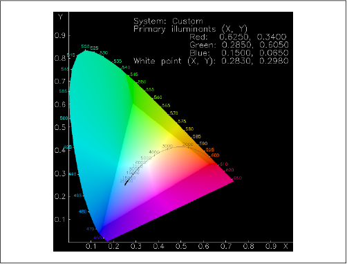 Figure 10-1: Typical chromaticity diagram. (Click for full-scale version.) |
Figure C-2 in the color insert, reproduced in grayscale as Figure 10-1, shows an interestingly shaped color blob with a numbered curve and a brighter triangle embedded in it and some numbers around its curved edge. The blob represents the complete range of hues and saturation levels that the human eye can discern; a true spectrum would wrap around the numbered edge[80] (albeit without the cyan region near the upper left). The middle is composed of smoothly interpolated mixtures, including ``white.'' The numbers on the axes give the x and y values of each hue and are directly related to the International Commission on Illumination's (CIE, for Commission Internationale de l'Éclairage) XYZ color space, a standard and device-independent color space for well over half a century. We'll come back to that shortly.
[80] The numbers give the wavelength (in nanometers) of the spectral colors along the edge. Visible light lies within the range 400 nm to 700 nm, roughly.
The brighter triangle in the middle represents the colors that can be displayed by a particular monitor (not including any brightness information) and is known as the color gamut of the display. The corners of the triangle give the maximum-intensity red, green, and blue hues; these directly correspond to the physical characteristics of the phosphors used in the display. LCDs, printers, color film, and even textile dyes have similar gamuts, though not always triangular. Perhaps the most striking feature is the fact that the monitor's gamut covers less than half of the complete color range. In other words, there are many colors that the human eye can perceive but that cannot be correctly represented on a monitor. The fact that the chromaticity diagram can be displayed on a monitor at all means that the region outside the triangle can be represented in some manner, just not the correct one. This is the source of the cyan error noted previously.
Because the diagram has been projected down from a three-dimensional color space (XYZ) to the two-dimensional xy plane, information about the relative intensities of red, green, and blue has been lost. That is, the x,y values for the red phosphor indicate what color it emits at any given intensity level and similarly for the green and blue phosphors. But we still need to know the relative intensities of the three phosphors when they are all at full power. This is where the concept of ``white'' comes in. In fact, there are many candidates for ``white,'' from the warm, yellowish whites produced by incandescent lightbulbs to the cool, bluish whites of electrical arcs and lightning.[81] The curved line in the middle represents all possible values of ``white'' for a given monitor, only one of which will be displayed as such. The associated numbers along the curve refer to the ``blackbody temperature'' or color temperature of any given white value; among other things, a star whose surface (photosphere) is at the given temperature will emit light of the given color most strongly. [82] Our Sun's surface temperature is around 6,000 degrees Kelvin, for example; not coincidentally, this is the color temperature most humans associate with ``average'' or ``true'' white.
[81] It is slightly odd that humans perceive redder light as ``warm'' and bluer light as ``cool'' when, in fact, the opposite is true. Lightning is far hotter than the filament in an incandescent bulb.
[82] Keep in mind that we are still talking about human perception. A blackbody emits a true continuum of light; a monitor emits a more limited continuum composed of three broad, overlapping curves--corresponding to the red, green, and blue phosphors. Humans perceive the monitor's ``white'' output to be the same as that of a blackbody at a particular temperature, but a spectrometer would say otherwise.
How does all of this relate to color correction in PNG? If the encoding software knows the locations of the three corners of the triangle (the primary chromaticities) and of white point, it can save these values in PNG's chromaticity chunk, cHRM. When the image is decoded on another system with a different color range, the decoder can convert the x,y chromaticity values of both systems into XYZ space, calculate any necessary adjustments between the two, and use that calculation to convert the RGB values of the image into XYZ space and then into the RGB space of the display system.
The simple way to deal with such conversions is to feed the information to a color management system (CMS), assuming one is present. All of the tricky details of conversion between different color spaces and of mapping different monitor gamuts are handled by the CMS. Color management systems are not yet in wide use on typical users' platforms, however; a decoding application that wishes to maintain optimal color fidelity will need to handle the conversions on its own. The calculations to do so are not terribly difficult, but they do involve a number of matrix operations. These are detailed in of the University of Manchester's excellent tutorial, Colour in Computer Graphics, and also in the "Color Tutorial" section of the PNG Specification, Version 1.1.
The structure of cHRM is shown in Table 10-2.
| Table 10-2. cHRM Chunk |
| Field | Length and valid range |
| White point x | 4 bytes (0-2,147,483,647) |
| White point y | 4 bytes (0-2,147,483,647) |
| Red x | 4 bytes (0-2,147,483,647) |
| Red y | 4 bytes (0-2,147,483,647) |
| Green x | 4 bytes (0-2,147,483,647) |
| Green y | 4 bytes (0-2,147,483,647) |
| Blue x | 4 bytes (0-2,147,483,647) |
| Blue y | 4 bytes (0-2,147,483,647) |
Each of the eight values is an unsigned long integer, equal to the actual floating-point value multiplied by 100,000 and rounded to the nearest integer. Like the gAMA chunk, cHRM must precede all IDAT chunks and, if present, PLTE; only one cHRM chunk is allowed.
The popularity of the RGB color space is at odds with its fundamentally device-dependent nature. In order to address this problem, a number of manufacturers of computer-related equipment and the International Color Consortium have cooperated to define a standard RGB space to which various devices such as monitors, printers, scanners, and electronic cameras can be calibrated. This specification, known as sRGB, is expected to be approved as an international standard by the International Electrotechnical Commission (IEC) by mid-1999; it will formally be known as IEC 61966-2-1.
sRGB allows one to create a PNG image on one system and print or display it on another with full color fidelity and without ever converting to XYZ or another device-independent color space. How well it works in practice remains to be seen, but a well-specified international standard--and manufacturers' evident interest in it--will go a long way toward ensuring that future devices are compatible at the RGB level.
In addition, an image that was created under sRGB can be flagged as such with very little overhead. Only one parameter, the rendering intent, is required; it is stored as a single byte in PNG's sRGB chunk. The rendering intent, also known as ``artistic intent,'' indicates how the creator of the image wishes the colors to be mapped when the output device's color gamut (recall the discussion in the previous section) does not match that of the original device. For example, imagine that an artist creates an image on an sRGB-compliant monitor and graphics system, and when he's finished he sends it to an sRGB-compliant color printer. Because the light-emitting phosphors of the monitor and the light-reflecting inks of the printer and its paper will be able to represent somewhat different ranges of colors--ideally, mostly overlapping, but conceivably with only a little overlap--it is necessary for the artist to specify how he wishes the different color gamuts of the devices to be mapped to each other.
The simplest rendering intent (in concept) is known as absolute colorimetric. The word ``colorimetric'' means color-measuring, and this intent indicates that, for the region of overlap between source and destination gamuts, any given pixel will be measured to have identical colors on the two devices. When the output device is not capable of reproducing some of the colors of the input device (i.e., the gamut is more restricted in that region of color space), the colors are clipped to the nearest color that can be reproduced. The result is that dynamic range will be lost in some areas. For example, suppose that the image has a smoothly varying blue gradient and that the output device is restricted to only the darker blues. The output will show a smoothly varying gradient progressing from darkest blue to medium blue, but then it will saturate and render all of the remaining gradient as a constant, medium blue. Likewise, the intensity range may be clipped if the output device is incapable of rendering absolute black or the brightest shades of white. This rendering intent might be used in cases in which three or more profiles are involved--for example, when an image created on a computer display is intended for a particular typesetter but first needs to be proofed on a local printer.
A similar intent is relative colorimetric. As with the absolute flavor, RGB values correspond to precise CIE color measurements, but they are modified according to the intensity range and color cast (i.e., the white point) of the output medium. Referring to our artist again, his monitor may be capable of displaying true, 5,000K CIE white, but the paper in his printer generally will not uniformly reflect all of the wavelengths that hit it, regardless of the source.[83] To put it another way, the paper will have a different white point than the monitor. As a result, it may be desirable to sacrifice perfect color correspondence in favor of a similar dynamic range in intensities, by referencing the RGB values to whatever paper or other output medium is used. The output image may have an overall lighter or darker appearance or an overall color shift, but there will be no clipping of grayscale gradients, and the colors will appear to match--thanks to the human visual system's tendency to acclimate to an overall tint or, to put it another way, to the ``prevailing white''. The relative colorimetric intent is the ICC's default; it might be desirable for displaying and printing corporate logos.
[83] And if he's silk-screening white T-shirts, no amount of bleach will change that. There are some detergents that infuse clothing with small amounts of phosphorescent chemicals in order to make ``whites whiter''; one's clothes are no longer strictly reflective, but actually glow slightly when exposed to blue or ultraviolet light. Such detergents are generally not part of an sRGB-compliant display system.
A still more approximate intent, but one that may capture more of the personality of the original image, is the perceptual rendering intent. The idea in this case is to map the full color ranges of source and destination devices as well as possible. This may involve either expansion, compression, or shifting of the color gamut. Even colors within the region where the gamuts overlap may be modified; in other words, absolute color fidelity is less important than preserving the dynamic range in both color and intensity of the image. This is often the most appropriate intent for rendering photographs.
Finally we have the saturation-preserving rendering intent, which is similar to perceptual rendering in that it doesn't necessarily enforce completely accurate color reproduction. But rather than favor overall gamut mapping like the perceptual intent does, this rendering intent specifies that the saturation of each color should remain constant. Saturation can be thought of as the amount of gray in a color of a given hue (say, greenish-aqua) and lightness. As the saturation approaches zero, the color approaches gray; maximum saturation gives the purest shade of the given hue. Since a cheap inkjet printer might have only two-thirds of the saturation range of an expensive dye-sublimation printer, colorimetric rendering might induce another kind of clipping in the inkjet's output. Saturation-preserving rendering would avoid that, but could possibly result in changes in hue and/or lightness. It might be the preferred intent for printing business charts and graphs.
PNG's sRGB chunk encodes the rendering intent with the same values specified by the International Color Consortium for ICC profiles: that is, byte value 0 for perceptual, 1 for relative colorimetric, 2 for saturation-preserving, and 3 for absolute colorimetric.
Because the sRGB color space encompasses gamma and chromaticity information, it is not strictly necessary for a PNG image to include gAMA and cHRM chunks in addition to the sRGB chunk. But since not all applications will know how to interpret sRGB, encoders should nevertheless include a gAMA chunk that corresponds to sRGB, and possibly a cHRM chunk as well. Decoders that know how to deal with cHRM are likely to know how to deal with sRGB, too, which is why cHRM may be omitted. The proper values for the two chunks are in Table 10-3.
An sRGB-aware decoder should ignore gAMA and cHRM whenever an sRGB chunk is present; the latter takes precedence. Less sophisticated applications can use gAMA and cHRM to render the image approximately as intended, even without knowledge of the sRGB color space. But note that there is no excuse for any application written after the PNG 1.1 specification not to recognize sRGB, at least; it is now part of the core spec, and new applications should know what gamma and chromaticity values correspond to it, regardless of whether the corresponding chunks--or even conflicting chunks--are actually present in the file. As with gAMA and cHRM, only one sRGB chunk is allowed, and it must appear before any PLTE and IDAT chunks.
| Table 10-3. sRGB Gamma and Chromaticity Values |
| gAMA | Image gamma | 45,455 |
| cHRM | White point x | 31,270 |
| White point y | 32,900 | |
| Red x | 64,000 | |
| Red y | 33,000 | |
| Green x | 30,000 | |
| Green y | 60,000 | |
| Blue x | 15,000 | |
| Blue y | 6,000 |
For ultimate control over color fidelity and issues of device dependence, PNG supports the ability to embed a full International Color Consortium profile via the iCCP chunk. The ICC profile format, at version 3.4 as of this writing, is a relatively mature specification that is itself headed toward ISO standardization. The format is capable of describing not only computer monitors, but also printers, scanners, liquid crystal displays, film, transparencies, and so forth.
Though the profile format itself is understandably quite complex, given all of the devices and color-space conversions it must encompass, the format of PNG's iCCP chunk is independent of all that. Similar to the zTXt chunk (which will be described in Chapter 11, "PNG Options and Extensions"), iCCP contains only four elements, as shown in Table 10-4: a printable name terminated by a null byte; a byte indicating the compression method; and the compressed profile itself.
| Table 10-4. iCCP Chunk |
| Field | Length and Valid Range |
| Profile name | 1-79 bytes (Latin-1 text) |
| Null separator | 1 byte (0) |
| Compression method | 1 byte |
| Compressed ICC profile | n bytes |
The profile name is for the convenience of the artist or user of the image; in practice, it will probably be similar to the profile description tag, which is embedded in the profile itself. The compression method byte currently must be zero, indicating a compressed stream in zlib format, using the deflate compression method. As with zTXt and the actual image data, a future major revision of the PNG spec may define other compression methods, in which case this byte will be allowed to take on other values.
Aside from uncompressing it, ordinary decoders will not be expected to know anything about the ICC profile other than the fact that they can be large (i.e., more than 64 KB); instead, they will simply hand it off to the local color management system for appropriate processing. Encoders should ensure two things: that the profile is a valid ICC profile and that it refers either to an RGB color space (for color images, including colormapped ones) or to a grayscale color space. CMYK color spaces, for example, are disallowed. Likewise, multiple copies of iCCP are disallowed; if the iCCP chunk is present, it must come before any PLTE or IDAT chunks.
By mid-1998, there were indications that something of a ``TIFF effect'' applied to the ICC profile format; that is, profiles from different vendors were not necessarily interoperable with each other or with different color management systems.[84] Presumably this will be worked out by the time the ICC specification becomes an official standard, but in the meantime, it is something of which PNG implementors should be aware.
[84] This is hardly surprising for a format that attempts to deal with such a thorny problem.